I had promised to start posting my activations so that others could start planning on how to find me. This weekend, I will be trying to get first on 902 and then 1296. There are just a few stations that will be getting on 902, but they seem to be spread out across local Friday, Saturday and Sunday afternoons. Weather permitting, I will try to work the few on 902 and then move over to 1296. This will not be optimum for stations with limited moon in common to me here in Oregon. Please do not worry that you will miss me. I will be in Oregon until early May.
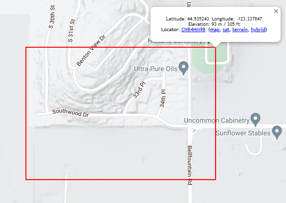
My location will be part way up the hill in this image. Grid location via K7FRY.com with Google Maps data.
I need about 15 degrees elevation to get over the near-field rooftops. I will always be on HB9Q when I have internet connectivity. I will likely not stay on until moon set. If you have a special need or want, please send me an email. It is listed at QRZ.com.
Updated – I did not attempt to get on during the 24th local time. The rain was too often and too much. On the 25th, I did get the system assembled and tried to get on 902 MHz. I made a mistake and blew one of my two 902 amplifiers. I need a day or two to finish the modification of the second amplifier. I will be more careful with it. After the final confirmation that the 902 amplifier was dead, I moved over to 1296 MHz. I worked a number of stations including KB2SA for his 49th state. I took a break for dinner, When I came back, the station would not function. I found that the USB hub had failed. I do not have a spare. I will need to replace it before I can try again on 902 and 1296.
For an informal operation, it was a bit of failure and success. I’ll take the success and learn from the failures. More to follow in other posts. Tentatively, I will make a larger effort on 1296 during my local Friday afternoon and evening, March 31 to April 1. This should allow for a better window to EU. I will be at a nearby farm with a much cleaner view of moonrise.
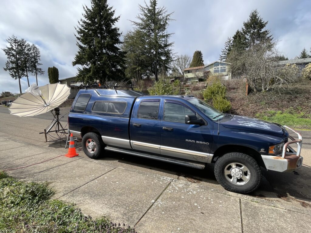
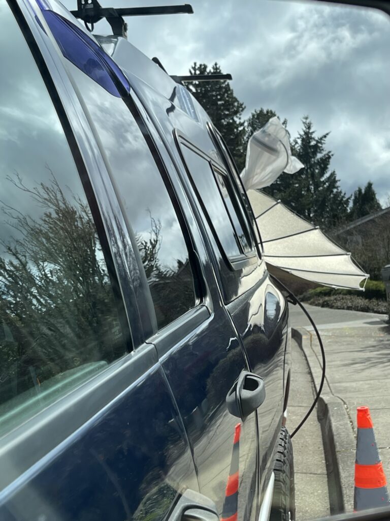
Operated from next to the curb with an extension cord from my parents’ house.This is a reflection image (reversed) looking from the operating position (passenger seat) toward the antenna through the side view mirror.
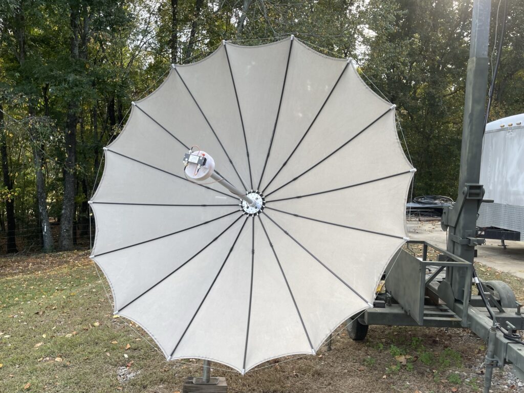
My 2.4m dish with 1296 patch feed from Paul, W2HRO, and Sub-Lunar Systems. This was as setup for receive testing during the October 2022 ARRL EME contest weekend.
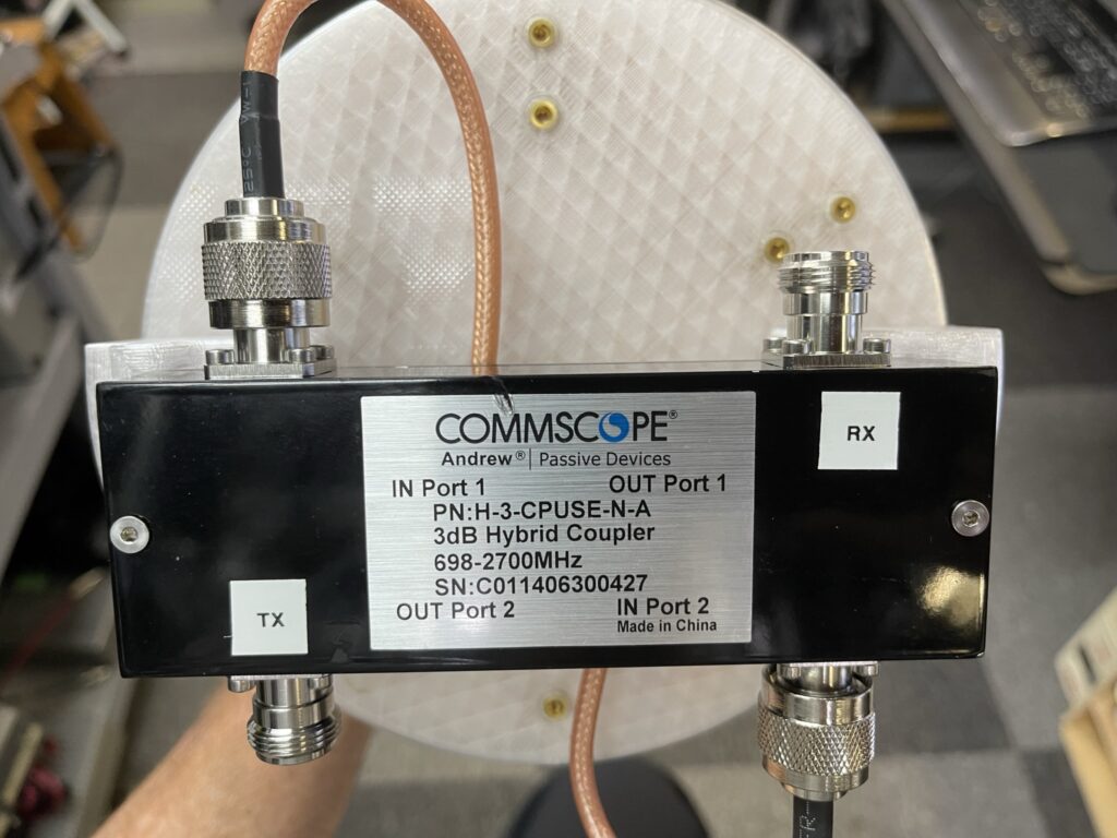
The feed configured for circular polarization is deceptively simple and even easier to put on the air. As shipped, the 90 degree hybrid is labeled for TX and RX.
Sub-Lunar Systems 1296 MHz feed connections at the 90 degree hybrid.
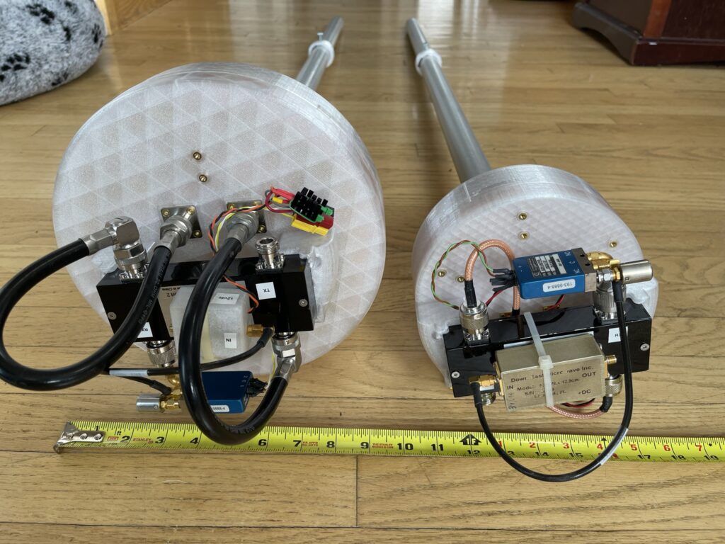
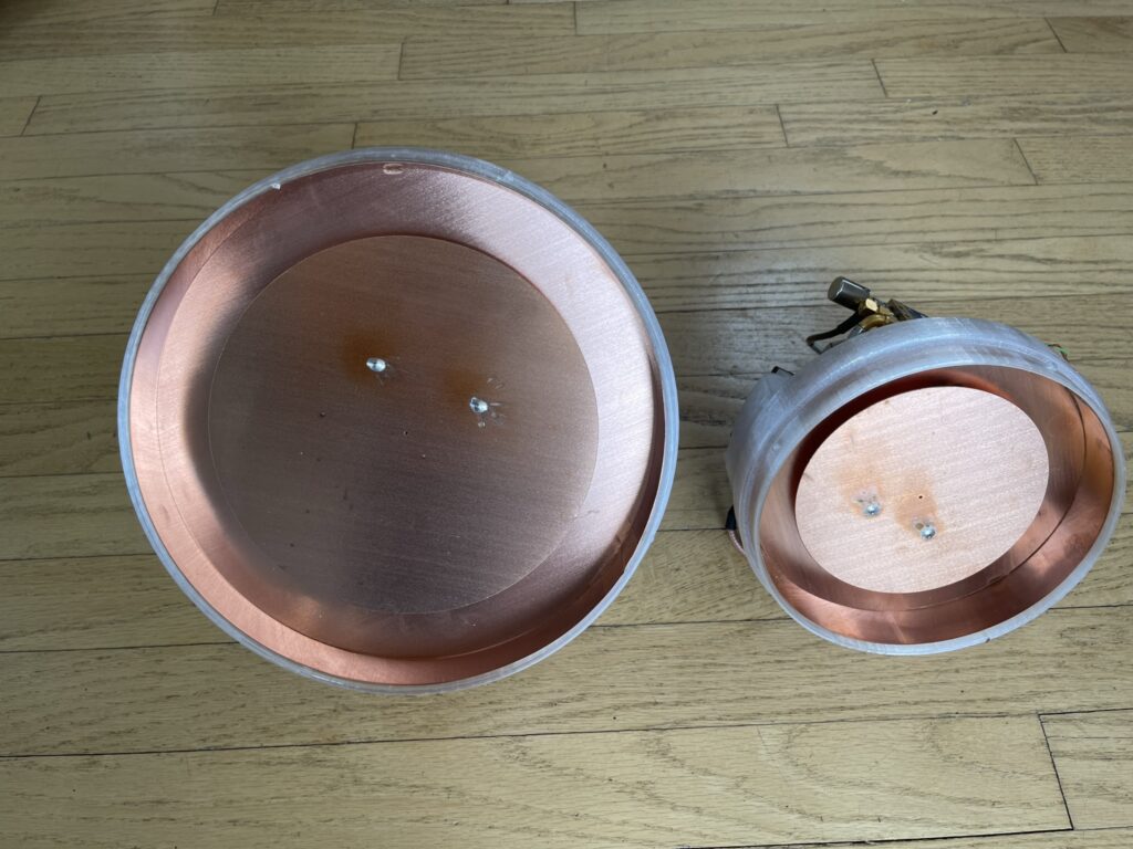
Here is a comparison photo showing the size difference of the 902 feed versus the 1296 feed as configured for NX9O Rover.
902 feed on the left and 1296 feed on the right.The patch side of the feeds with 902 on the left and 1296 on the right.
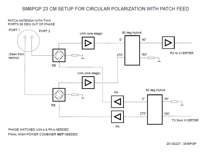
Paul’s feeds are based on patch feeds from SM6PGP. I found a detailed description in a Swedish EME-meeting May 2013 paper, “Circularly Polarized Patch Feed for 1296 MHz”, published by SM6FHZ and SM6PGP. Toward the end of the presentation there is a suggestion of a good way to setup the feed for circular polarization.
While this method of connecting the feed for circular polarization is quite comprehensive, for field use, it is way too complex. It is much simpler to use split transmit and receive lines, put the LNA at the feed, and use a small RF relay to protect the LNA during transmit. I tried to source suitable 12VDC SMA relays for my feeds, but the relays I was shipped turned out to be latching and not failsafe. Getting failsafe versions of these SMA relays is much easier at 24-28VDC. That is what I ended up doing. I rewired the control cable to the feed to add a pair of lines for 24VDC relay control to go along with the 12VDC LNA power. These two lines are enabled when I turn on the sequencer, and are dropped by the sequencer when going into transmit. At some point I’ll add a block diagram to this page to show exactly how I did it.
Purists will point out that maybe I did it wrong. The decision to provide more protection to the LNA’s was deliberate. I might have a minor amount of discontinuity to my circular polarity and/or impedance mismatch during transmit by having the RX port effectively unterminated. It is a conscious decision. On 1296 with up to 500w I have more than enough power to make up for the discontinuity. On 902 it seems to be relatively circular based on the few reports I have been given so far with less than 200w. I am hoping to be able to improve my transmit output level during this next year on 902.
The other choice that some may quibble about is that of circular polarization instead of linear with the ability to switch between horizontal and vertical. I agree that would be more compatible with most of the existing stations on 902. As a newcomer to 902, I am fighting the history. I have seen how easy it is to concentrate on the rest of the factors and not have to even think about faraday or polarization mismatch when using circular polarization on 1296. The fewer things that need my attention when I try to activate a new location, the better. The 902 and 1296 feeds are completely plug compatible in my system.
This summer I expect to add 2304 MHz. My new feed has already arrived from W2HRO to my home in Georgia. If all goes well with amplifier retuning, I will have 140w or more. It should be a lot of fun. I hope to put on many states, but I probably will not ever reach the level of dedication that KA6U has shown in making his activations. I hope to work all of you many times.
This post is not complete. It will continue to change. I will remove this paragraph when I am done. It will be a long one. It has been backdated to the completion date of the amplifier as I used it during the November 2022 weekend of the ARRL EME contest.
As I started to work through the list of major modules needed for an EME rover, I quickly found that lead times for 1296 MHz amplifiers were too long for my first hoped departure of mid-November, 2022. Significant amplifiers for 23cm are also a bit pricey, and my first choice from complete turn-key W6PQL amplifier is not available for the foreseeable future. Looking through all the options I noticed that KB7Q had rolled his own amplifiers multiple times using W6PQL pallets.
I chose to order the fully assembled 1296MHz pallet and support circuits that I thought I would use. I floundered around a bit figuring out the configuration. I ended up with a quite capable amp. I used W6PQL’s control board and 50V FET switch in my amplifier. These used in the amplifier so far, but I bought more modules and intend to upgrade further. I had some significant coaching from KB7Q who was very helpful answering some of my questions about how to proceed. I like Gene’s KISS approach. The schematic is from his August 2021 presentation to NTMS:
KISS Layout VHF/UHF Amps, KB7Q Feb. 2021
My amplifier ended up a bit more complex than Gene’s, but it was still close to his ideal. I prefer to use only one power supply voltage to an amplifier. KB7Q’s method is very simple, but requires 50VDC and 12VDC supplies. I intended to mount the amplifier in the covered bed of my truck. I reasoned that the heat generated might make the truck interior a bit warm and moving the amplifier closer to the dish would reduce coax losses.
The W6PQL control board has many functions available. I liked the idea that thermal fault inhibit was so easy to implement. The temperature sensor is included in his control board kit. The board is setup to provide bias to the power FET switched with PTT. It is also able to provide low current 12VDC when the TIP102 regulator is installed. A word of warning though, using the TIP102 circuit really needs a current limiting resistor as the supply is drawn from the 50VDC. For the 50VDC reduction to 13.5VDC, a 25 ohm 25 watt resistor is recommended. I missed that detail in my first readings of the control board documentation. Mail order parts to the rescue.
<Brian amplifier version photo and schematic to be inserted here>
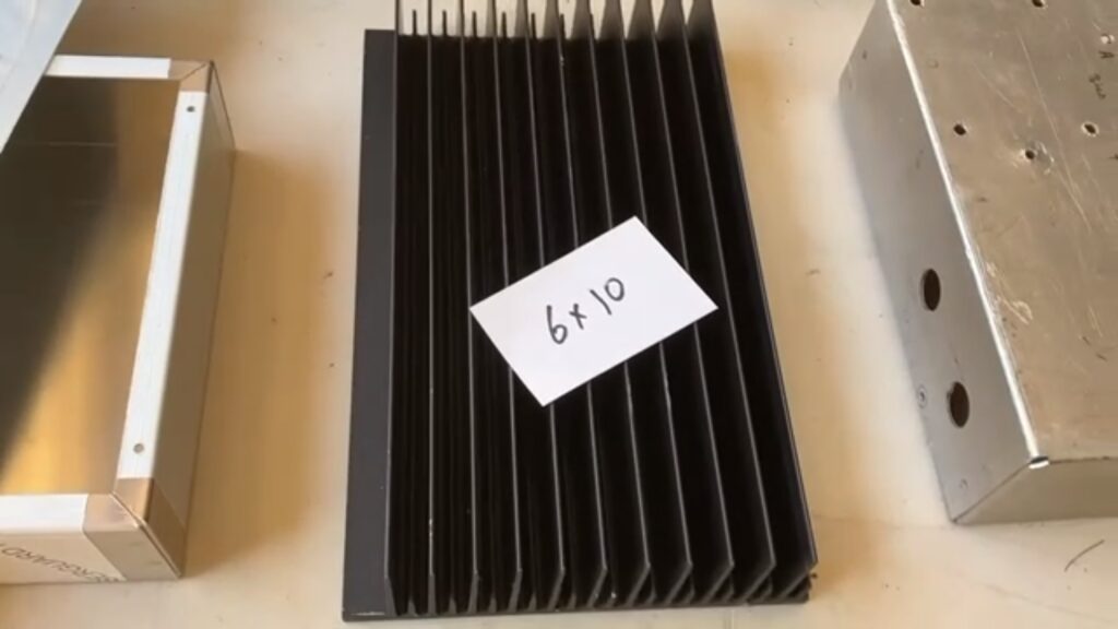
When I was reviewing the cabinet and heat sink requirements I saw what W6PQL says this about heat sinks at the bottom of his ‘parts I can supply‘ page, “I no longer supply heat sinks as a part, but you can still purchase the material directly from www.heatsinkusa.com. The amplifiers use the 10.080 inch extrusion, which weighs roughly 1 pound per inch of length. For amplifiers up to 1kw, and for the 1.5kw VHF amplifiers, order a 6-inch length. For 1.5kw HF amplifiers like the HF2000, you will need a length of 10 inches…or you can use two of the 6-inch pieces. Use the drilling templates supplied with your amplifier kits as a guide to drill and tap.” So the candidate heat sink should be roughly 6 lbs. of aluminum (or better) and roughly 6 inches by 10 inches.
W4ZST helped me with so many parts of this amplifier. I would not have been able to complete it so quickly without his help. He located a selection of cabinets and heat sinks to choose from to house and help cool the pallet.
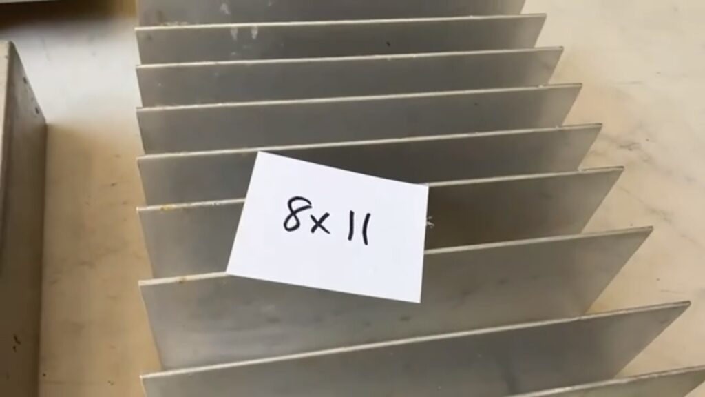
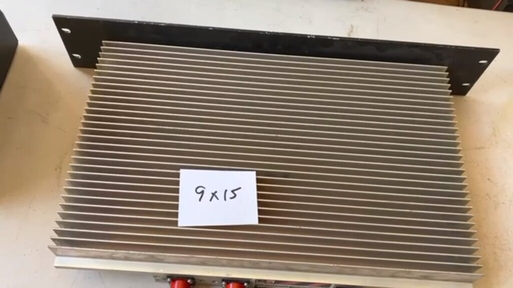
Heat Sink Candidate 1 – 6″ x 10″, but the fins seemed short and the weight was a bit lightHeat Sink Candidate 2 – 8″ x 11″, with nice tall fins that seemed too widely spacedHeat Sink Candidate 3 – 9″ x 15″, with fins that were a bit short, but the base material was thicker and the heat sink weighed 13 lbs.
“Candidate 3″ shown above is what I decided to use. At 9″ by 15″, with a thicker base material and lots of fins, Bob, W4ZST, and I measured the weight of this one as 13 lbs. I realized this was more than enough material to dissipate the heat generated by the pallet. This heatsink was originally a commercial ~453MHz transmitter combiner with 3 or 4 inputs. From the interior I was able to salvage dummy loads and RG213 double shielded N-male jumpers. A bonus feature was the 19” rack mount face that I might use in the future depending on how I “permanently” mount the amplifier.
<Case selection and preparation to be added here>
<More details and performance…>
On his page, https://www.w6pql.com/high_power_amplifier_for_1296.htm, W6PQL notes that Eccosorb is used, “…to dampen resonances produced inside cavities like the one created when the cover is in place.” I had some similar material and put it in case cover opposite the RF pallet.
The absorptive mat I added to the inside cover surface facing the RF pallet. It may not be the “perfect” choice, it was a piece I had for many years finally put to good use.