This post is not complete. It will continue to change. I will remove this paragraph when I am done. It will be a long one. It has been backdated to the completion date of the amplifier as I used it during the November 2022 weekend of the ARRL EME contest.
As I started to work through the list of major modules needed for an EME rover, I quickly found that lead times for 1296 MHz amplifiers were too long for my first hoped departure of mid-November, 2022. Significant amplifiers for 23cm are also a bit pricey, and my first choice from complete turn-key W6PQL amplifier is not available for the foreseeable future. Looking through all the options I noticed that KB7Q had rolled his own amplifiers multiple times using W6PQL pallets.
I chose to order the fully assembled 1296MHz pallet and support circuits that I thought I would use. I floundered around a bit figuring out the configuration. I ended up with a quite capable amp. I used W6PQL’s control board and 50V FET switch in my amplifier. These used in the amplifier so far, but I bought more modules and intend to upgrade further. I had some significant coaching from KB7Q who was very helpful answering some of my questions about how to proceed. I like Gene’s KISS approach. The schematic is from his August 2021 presentation to NTMS:

My amplifier ended up a bit more complex than Gene’s, but it was still close to his ideal. I prefer to use only one power supply voltage to an amplifier. KB7Q’s method is very simple, but requires 50VDC and 12VDC supplies. I intended to mount the amplifier in the covered bed of my truck. I reasoned that the heat generated might make the truck interior a bit warm and moving the amplifier closer to the dish would reduce coax losses.
The W6PQL control board has many functions available. I liked the idea that thermal fault inhibit was so easy to implement. The temperature sensor is included in his control board kit. The board is setup to provide bias to the power FET switched with PTT. It is also able to provide low current 12VDC when the TIP102 regulator is installed. A word of warning though, using the TIP102 circuit really needs a current limiting resistor as the supply is drawn from the 50VDC. For the 50VDC reduction to 13.5VDC, a 25 ohm 25 watt resistor is recommended. I missed that detail in my first readings of the control board documentation. Mail order parts to the rescue.
<Brian amplifier version photo and schematic to be inserted here>
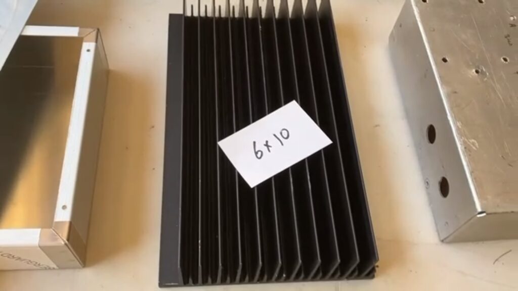
When I was reviewing the cabinet and heat sink requirements I saw what W6PQL says this about heat sinks at the bottom of his ‘parts I can supply‘ page, “I no longer supply heat sinks as a part, but you can still purchase the material directly from www.heatsinkusa.com. The amplifiers use the 10.080 inch extrusion, which weighs roughly 1 pound per inch of length. For amplifiers up to 1kw, and for the 1.5kw VHF amplifiers, order a 6-inch length. For 1.5kw HF amplifiers like the HF2000, you will need a length of 10 inches…or you can use two of the 6-inch pieces. Use the drilling templates supplied with your amplifier kits as a guide to drill and tap.” So the candidate heat sink should be roughly 6 lbs. of aluminum (or better) and roughly 6 inches by 10 inches.
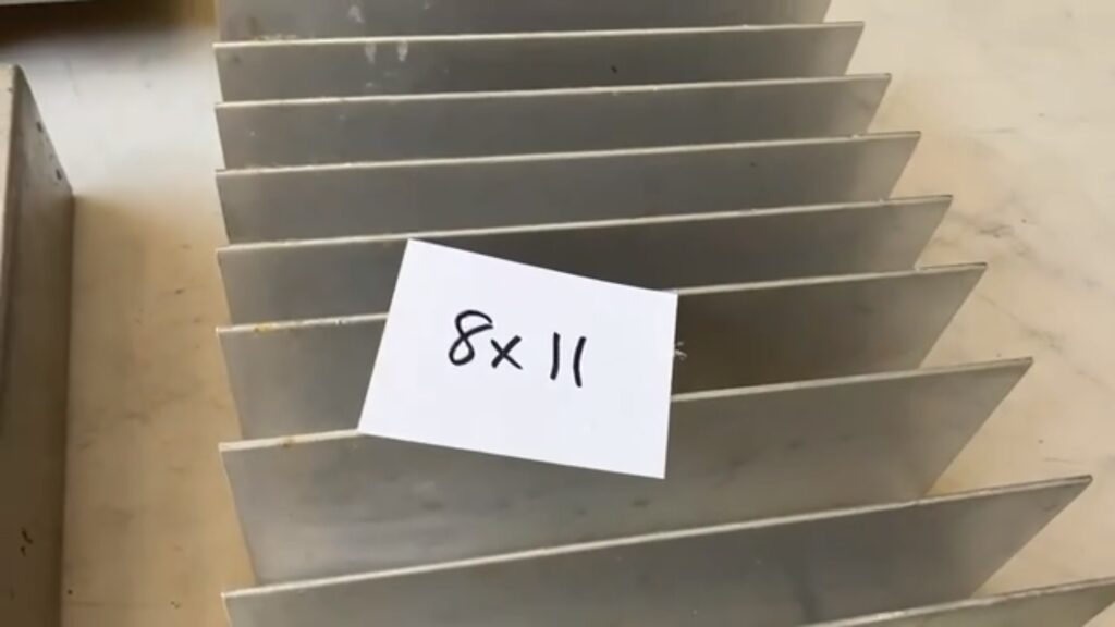
W4ZST helped me with so many parts of this amplifier. I would not have been able to complete it so quickly without his help. He located a selection of cabinets and heat sinks to choose from to house and help cool the pallet.
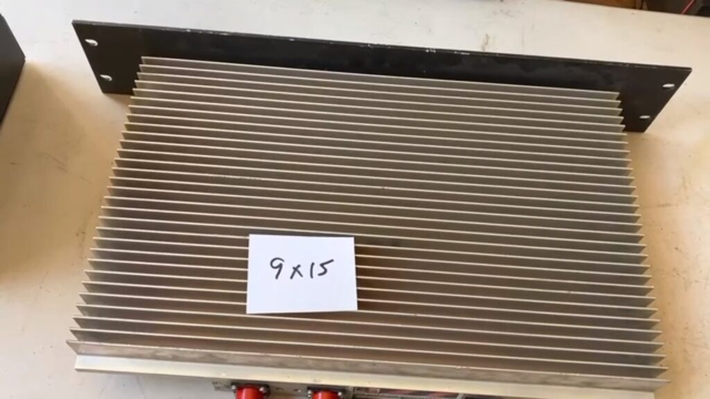
“Candidate 3″ shown above is what I decided to use. At 9″ by 15″, with a thicker base material and lots of fins, Bob, W4ZST, and I measured the weight of this one as 13 lbs. I realized this was more than enough material to dissipate the heat generated by the pallet. This heatsink was originally a commercial ~453MHz transmitter combiner with 3 or 4 inputs. From the interior I was able to salvage dummy loads and RG213 double shielded N-male jumpers. A bonus feature was the 19” rack mount face that I might use in the future depending on how I “permanently” mount the amplifier.
<Case selection and preparation to be added here>
<More details and performance…>
On his page, https://www.w6pql.com/high_power_amplifier_for_1296.htm, W6PQL notes that Eccosorb is used, “…to dampen resonances produced inside cavities like the one created when the cover is in place.” I had some similar material and put it in case cover opposite the RF pallet.
